Task 1 Scene level
3 classes (pixel/object/structural levels)
 |  |  |
| (a) Pixel level | (b) Object level | (c) Structural level |
Figure 1 Scene level
From Figure 1, determining the scene level classification is the initial task; subsequent tasks are pursued according to different levels. Because images collected from reconnaissance efforts broadly vary in terms of distance, camera angles, emphasized targets, etc., the initial establishment of the scene level can help decrease the doubt of scale issue in images and reduce the complexity of subsequent tasks. Through filtering out the irrelevant data and dividing images more granularly into different levels, the classifiers for subsequent tasks can achieve an improved recognition performance. In the current Φ-Net framework, the benchmark scene level task is defined with three classes: pixel level (P), object level (O), and structural level (S). An image taken from a very close distance or only containing part of the component belongs to “P” [Figure 1(a)],; An image taken from mid-range and involving major targets such as a single structural component or multiple components belongs to “O” [Figure 1(b); An image, taken from a far distance and containing most parts of the structure or identifying its outline belongs to “S” [Figure 1(c)].
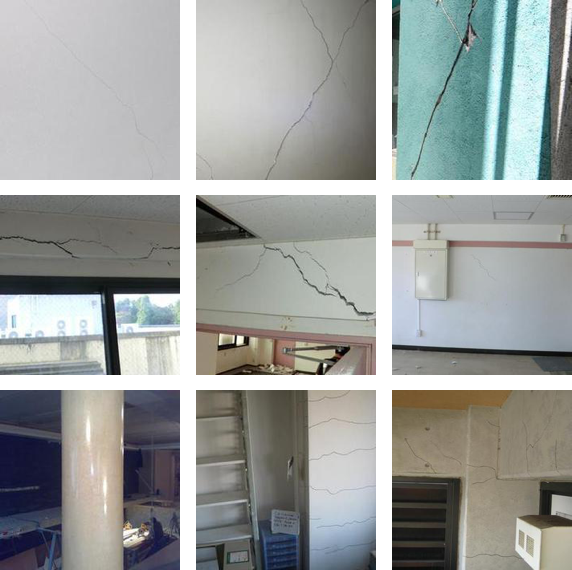
Task 2 Damage state
2 classes (undamaged/damaged)
 |  |
| (a) Undamaged | (b) Damaged |
Figure 2 Damage state
In the vision-based SHM, the damage state is one of the most important indices for structural health. In this task, the definition is straightforward: any observable damage pattern on the structural surface implies the damaged (D) case [Figure 2(a)]; otherwise, it is undamaged (UD) [Figure 2(b)].
Task 3 Spalling condition
2 classes (spalling/non-spalling)
 |  |
| (a) Spalling | (b) Non-spalling |
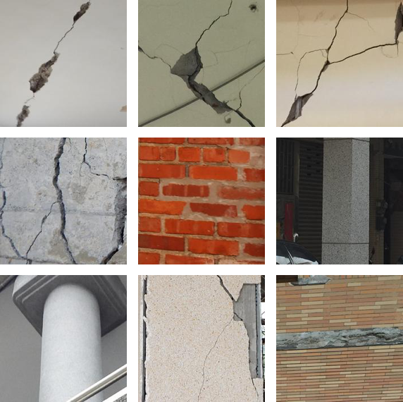
Figure 3 Spalling condition
Spalling is usually defined as flakes of material that break off from a component or pertains to loss of cover of the component’s surface. It often occurs in concrete and masonry structures, which may lead to severe consequences due to a reduction in the cross section and acceleration of corrosion in reinforcing steel bars. Spalling can be induced by expansion forces produced chemically or mechanically. Note most spalling images here were collected from post-earthquake reconnaissance effort. In other words, spalling patterns in Φ-Net dataset are mainly due to earthquake loading. In this task, the spalling condition is a binary classification task with only two classes: spalling (SP) [Figure 3(a)] and non-spalling (NSP) [Figure 3(b)].
Task 4 Material type
2 classes (steel/other materials)
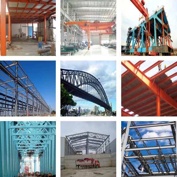 |  |
| (a) Steel | (b) Other materials |
Figure 4 Material type
Due to their mechanical properties, structural materials have a significant impact on structural response. Thus, identifying the type of material used for the structural component is important. The commonly used materials are steel, concrete, masonry, and wood. One of the difficulties in this task is that structural components are usually covered with non-structural components, e.g., plaster, making it difficult to accurately identify the material type from surface images. However, some structures and components are made from exposed steel members such as braces and plates, which makes it simply to identify them based on their shape and surface texture. In this task, simplifications were made to limit the classification to two types: steel (ST) [Figure 4(a)] and other materials (OM) [Figure 4(b)].
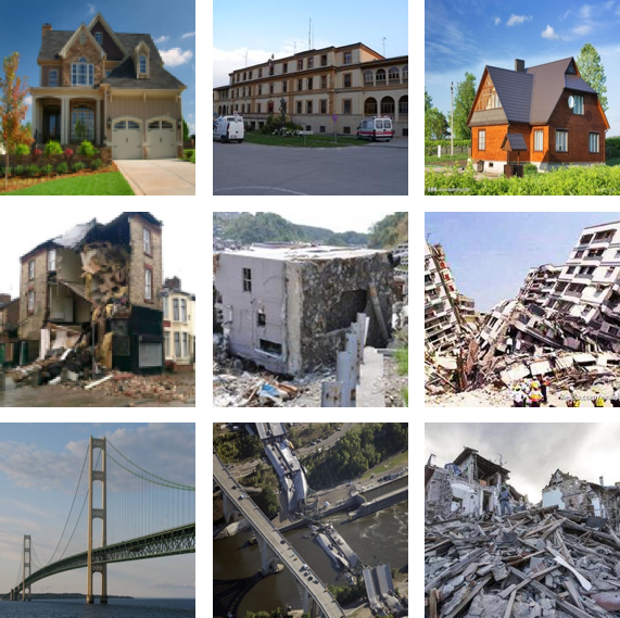
Task 5 Collapse mode
3 classes (non-collapse/partial collapse/global collapse)
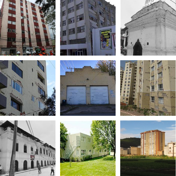 |  |  |
| (a) Non-collapse | (b) Partial collapse | (c) Global collapse |
Figure 5 Collapse mode
Due to different photographic distances, camera angles, etc., it is reasonable to evaluate the severity of damage based on different scene levels. In the view of structural level images, which contain the global information of the structure, the global performance of the structure––collapse mode––is of the greatest concern. In terms of structural mechanics, herein collapse mode is defined as non-collapse (NC), partial collapse (PC), and global collapse (GC): NC [Figure 5(a] includes undamaged or slightly damaged patterns but the structure remains intact; PC [Figure 5(b)] corresponds to only part of the structure having collapsed while the remaining parts are still intact; and GC [Figure 5(c)] represents catastrophic damage in the structure or evident permanent global excessive deformation.
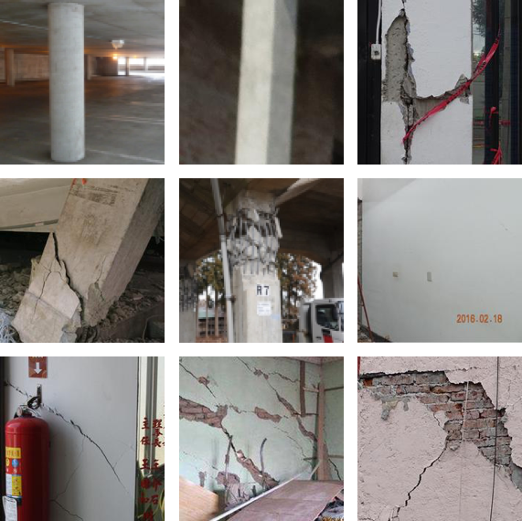
Task 6 Component type
4 classes (beam/column/wall/others)
 |  |  | 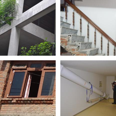 |
| (a) Beam | (b) Column | (c) Wall | (d) Others |
Figure 6 Component type
In a structural system, different structural components play different roles. Vertical components, i.e., columns and shear walls, provide lateral stiffness to resist lateral force induced by earthquakes; horizontal components, i.e., beams, diaphragms, and joints, transfer the horizontal load to the vertical components. In the seismic design of buildings, engineers have adopted concepts like “strong-column–weak-beam” and “strong-joint–weak-component” to define the role they play in providing resistance to ground shaking [Moehle 2014]. Thus, identifying the type of structural component is informative for SHM. From the hierarchical relationship established in the Φ-Net framework, structural component type identification is considered as a subsequent task at the object level by four classes: Beam [Figure 6(a)], Column [Figure 6(b)], Wall [Figure 6(c)], and Others [Figure 6(d)]. Note: it is challenging to identify from images whether a wall is a shear wall or an infill wall, even though they have major differences in how they provide lateral stiffness to the system. Thus, both types are grouped herein into one category. For components other than beams, columns, or walls, they are treated as other structural components, e.g., joints, staircases, braces, or even non-structural components such as windows, doors, etc.
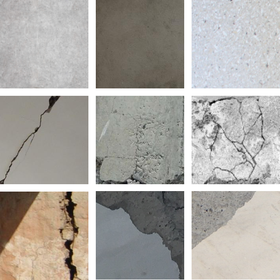
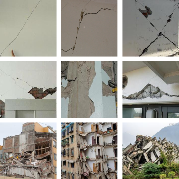
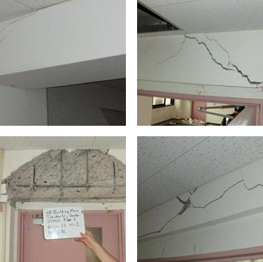
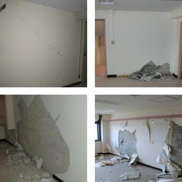
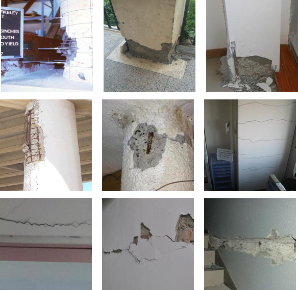
Task 7 Damage level
4 classes (undamaged/minor/moderate/heavy damage)
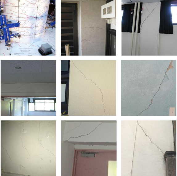 |  |  |
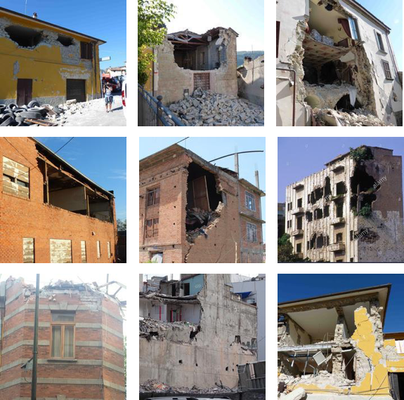
| (a) Minor damage | (b) Moderate damage | (c) Heavy damage |
Figure 7 Damage level
This task refers specifically to damage level evaluation of pixel and object level images, to complement the collapse mode task at the structural level. It is defined by four classes: Undamaged (UD), minor damage (MiD), moderate damage (MoD), and heavy damage (HvD); UD here is the same as that defined in the Task 2 damage state. As shown in Figure 7(a), MiD implies that there are only small and narrow cracks or a few spots were very minor spalling occurred on the cover of structural components. As the extent of the damage increases, cracks become wider and evidence of more extensive spalling occurs in areas but without failure, indicating MoD; see Figure 7(b). Shown in Figure 7(c), HvD means the damaged area is large, and the structural component is approaching failure.
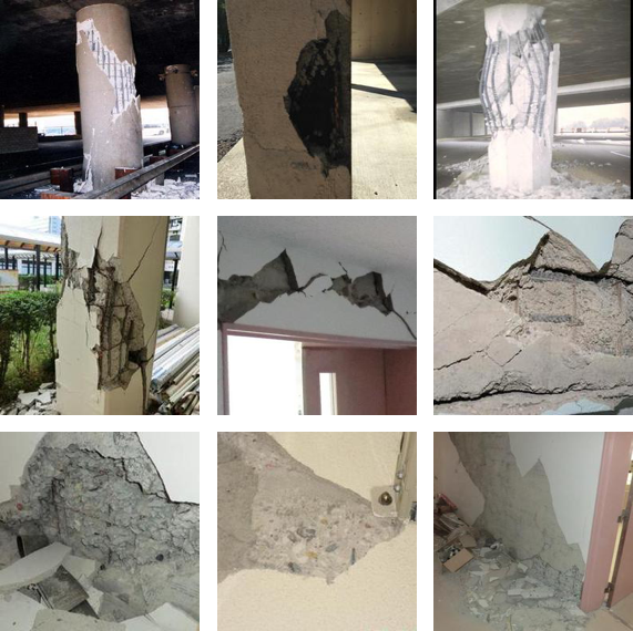
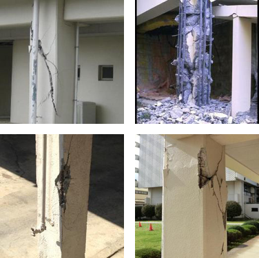
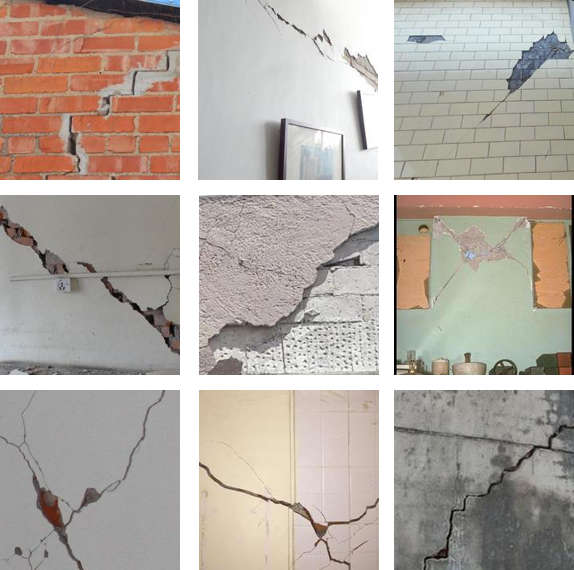
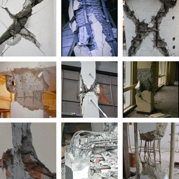
Task 8 Damage type
4 classes (undamaged/flexural/shear/combined damage)
 |  |  |
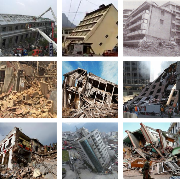
| (a) Flexural damage | (b) Shear damage | (c) Combined damage |
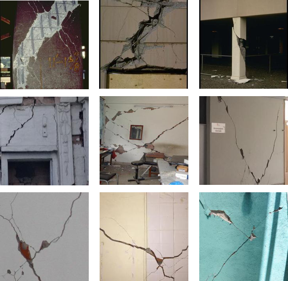
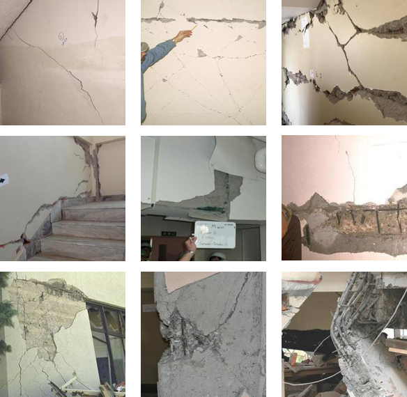
Figure 8 Damage type
Damage type is a more complicated and abstract classification task. Not restricted to a specific damage representation, e.g., reinforcement bar buckling, concrete spalling, etc., here, damage type refers to a complex and abstract semantic vision pattern, defined as flexural (FLEX), shear (SHEAR), and combined (COMB). These damage types have direct implications on mechanical properties and seismic design. Analogous to the failure types introduced in Moehle [2014], that is, flexural, shear, etc., and based on engineering judgment, label definitions were as follows:
1. If most cracks occur in the horizontal or the vertical directions or at the end of a component with respective vertical or horizontal edges, it was considered flexural-type damage as shown in Figure 8(a);
2. If most cracks occur in a diagonal direction or form an “X” or “V” patterns, it was considered shear-type damage as shown in Figure 8(b); and
3. If the distribution of cracks was irregular or accompanied with heavy spalling, it was considered combined-type damage as shown in Figure 8(c).
According to the domain knowledge, FLEX represents ductile failure, and it is a more desired pattern of failure than SHEAR, which leads to brittle failure. Thus, it is expected that damage types defined with concepts from seismic design will be very useful for the decision-making procedure.
Reference
1. Gao, Y. and Mosalam, K. M. (2019). PEER Hub ImageNet (Φ-Net): A Large-Scale Multi-Attribute Benchmark Dataset of Structural Images, PEER Report No.2019/07, Pacific Earthquake Engineering Research Center, University of California, Berkeley, CA.
2. Gao Y., Mosalam K.M. (2018). Deep Transfer Learning for Image-based Structural Damage Recognition, Comput-Aided Civil and Infrastructure Engineering, 33(9): 748-768.
3. Moehle J.P. (2014). Seismic Design of Reinforced Concrete Buildings, McGraw Hill Professional, New York, NY.