by Rodolfo B. Sancio
FIELD INVESTIGATION PROGRAM
A total of 42 CPT’s, of which 11 included seismic profiling by means of a pair of geophones incorporated in the cone penetrometer, in combination with 30 exploration borings were performed at selected sites in the city of Adapazari. These sites were selected based on their performance after the August 17, 1999 Kocaeli earthquake.
The following lines describe the methods and procedures followed for site investigation, namely:
Cone penetration tests (CPT's) were performed by Zemin Teknolojisi, A. S. (ZETAS) and the instruments used were manufactured by A. P. van den Berg, a Netherlands based company. Table 1 lists the specifications of the equipment employed, which consists of a 60° cone, with a cross-sectional area of 10 cm2. The friction sleeve, located above the tip, has an area of 150 cm2. Figure 1 shows the dimensions of the cone and the standards followed in its fabrication.
The piezocone has the filter located behind the cone, between it and the friction sleeve. The cross-sectional area at the location of the filter is 7.5 cm2, hence the cone area ratio is 0.75 as depicted in Figure 2.
The length of the rod increment used was 50 cm and the depth interval at which the tip resistance, sleeve friction, and pore water pressure were measured was 2 cm. The penetration speed was kept, in as much as possible, at 2 cm/s.
Tip Area |
10 cm2 |
Internal Angle of Cone |
60° |
Sleeve Area |
150 cm2 |
Cone Area Ratio |
0.75 |
Penetration Speed |
2 cm/s |
Measurement Interval |
At every 2 cm |
Rod Interval Length |
50 cm |
SEISMIC CONE PENETRATION TEST (SCPTU)
Down hole seismic wave profiling was performed using a cone instrumented
with two geophones separated 1 meter apart. The source for both shear and
compressive waves, as shown in Figure 3, consisted of a wooden log with
metallic plates located at both ends and on the upper center. As shown in
Figure 4, the first are for the generation of shear waves on either side
of the cone, and the latter for generating compressive waves.
The use of two geophones allows to obtain the seismic velocity of the layer
of soil between them.
 |
 |
EXPLORATORY BORINGS AND STANDARD PENETRATION TEST (SPT)
As has been extensively studied, the percentage of the total theoretical energy delivered to the split spoon sampler, or energy ratio, is strongly influenced by many factors such as: type of hammer release equipment, expertise of the operator, size of the cathead, diameter of the cathead, diameter of the rope, number of wraps of the rope around the cathead, hammer type, borehole diameter, rod length, rod diameter, tightness of the rod joints, verticality of the rod string, type of sampler, and others.
This problem was recognized, and in an attempt to standardize the test, procedures stipulated in ASTM D 6066-98 and ASTM D 1586 were followed. Table 2 presents a list of the methods used to perform the SPT in the Adapazari soils.
The exploratory borings were performed by ZETAS using the equipment shown in Figure 5. The drilling machine used was custom made in Ankara, Turkey and is the equivalent of a Crealius XC90H with 32 hp of power. The tower has an elevation of 6 meters above the ground.
The Solid Flight Auger (SFA) shown in Figure 6, was used initially to drill through pavement, rubble and hard ground above the water table.
The rotary wash drilling technique using a tri-cone drill bit, shown
in Figure 7 and Figure 8, was used to reach the depth at which the SPT was
to be performed. Casing was used to support the walls of the boring. The
casing was advanced to a depth of 5 to 10 cm above that at which the SPT
was to be performed. The last 30 cm were advanced without the use of water.
Rotary wash was then used to reach the depth at which the test was to be
performed.
 |
 (Photo by Jonathan D. Bray) |
 (Photo by Rodolfo B. Sancio) |
 (Photo by Jonathan D. Bray) |
Drilling Technique |
Rotary Wash |
Borehole Support |
Casing, ID = 10 cm |
Drill Bit |
Tri-cone bit, 9 cm diameter |
Drill Rod |
AWJ Type (Area = 5.94 cm2) |
Length of Rod Section |
152 cm (5 feet) |
Sampler |
O.D. = 50.8 mm I.D. = 35 mm (constant) Length = 600 mm |
Cathead Diameter |
11.2 cm |
Rope Diameter |
2 cm |
Rope & Cathead |
2 1/4 turns on a clockwise rotating cathead |
Hammer Type |
Safety Hammer |
Penetration Resistance |
Blows recorded over three intervals, each of 15 cm. N = number of blows over the last 2 intervals. |
A rope and cathead system was used to perform the Standard Penetration
Test. The diameter of the rope used was 2 cm and the diameter of the cathead
was approximately 11.2 cm. The driving energy was delivered by the 76 cm-high
drop of a safety hammer weighing approximately 63.5 kgf. The safety hammer,
shown in Figure 9, was custom made in Ankara, Turkey following the specifications
described in Kovacs, 1983.
 (Photo by Jonathan D. Bray) |
The rod string consisted of 1.5 m-long (5 feet) AWJ rods as shown in
Figure 10, which have a cross-sectional area of 5.94 cm2.
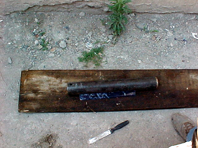
The sampler used is shown in Figure 11 and has an outer diameter of 50.8
mm (2 inches), a constant inner diameter of 35 mm (1 3/8 inch) and a total
length of 600 mm .
 |
 (Photo by Jonathan D. Bray) |
Although the methods and procedures used for this test comply with ASTM 6066-98 and ASTM 1586, additionally, and to be able to normalize as accurately as possible the blow count number to 60% of the theoretical energy, the energy delivered by the system was measured for each blow of the hammer. This measurement was done by instrumenting a portion of the rod string with two accelerometers and two strain gages as shown in Figure 12.
When the rod string is suddenly loaded by the impact of the falling hammer,
a compression wave travels down to the sampler penetrating it into the ground
in only fractions of a second. Further reflections of this wave travel upwards
and downwards until all the energy is dissipated. The integration of the
waves over time permits the calculation of the energy delivered by the system.
 (Photo by Rodolfo B. Sancio) |
 (Photo by Rodolfo B. Sancio) |
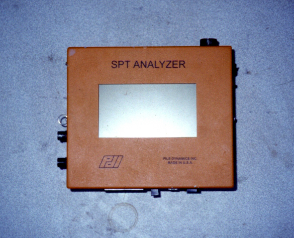
This seemingly difficult task is performed automatically by a stress
wave measurement system such as the SPT AnalyzerTM
commercialized by Pile Dynamics Inc. shown in Figure 13 and used in our
investigation. A typical record of the force and particle velocity imposed
to the rods by the impact of the hammer is depicted in Figure 14.
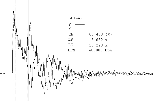 For this particular example the transmitted energy, ER is 60.4%.. |
Using the average energy ratio for each test, ER, and Equation 1 as recommended by Seed et al. (1985), the blowcount normalized to 60% of the theoretical energy, N60 can be computed.
When the soil type was suitable, "undisturbed" soil samples were obtained using a 50 cm-long, 70 mm OD and 64 mm ID steel Shelby type tube as shown in Figures 15 and 16. This tube was pushed into the soil at a constant rate with the aid of the hydraulics of the drilling rig.
Once brought back to the surface, the soil inside the tube was described
visually and each of it's sides were covered with wax to avoid moisture
migration.
 |
 (Photo by Rodolfo B. Sancio) |
A GEONOR H-10 field shear vane borer was used to obtain peak and residual undrained strength of the soil in boring SPT-A4. The height and diameter of the rectangular vane used, shown in Figure 17, was 110 mm and 55 mm respectively in compliance with the 2:1 ratio specified in ASTM D 2573-94.
Figure 18 depicts the vane boring instrument from which the torque is transmitted to the vane, and the readings are taken.
The vane shear test was performed 40 to 50 cm below the drilling depth
and the rate at which the test was performed was approximately 0.2°
per second.
 |
(Photo by Rodolfo B. Sancio) |
ACKNOWLEDGMENTS
The list of names of the people whose contribution made this project
possible is too long to mention as it includes the ZETAS
field crew shown in Figures 19 and 20, and office staff as well. The field
expertise of Mr. Sermet Daneshfar, Mr. Serdar Elgün, and Mr. Tufan
Heris is greatly appreciated.
 |
 |
REFERENCES
ASTM, (2000). Standard Practice for Determining the Normalized Penetration Resistance of Sands for Evaluation of Liquefaction Potential (ASTM D 6066-96). Annual Book of ASTM Standards, Vol. 04.09.
ASTM, (1996). Standard Test Method for Field Vane Shear Test in Cohesive Soil (ASTM D2573-94). Annual Book of ASTM Standards, Vol. 04.08.
Kovacs, W. D., Salomone, L. A., and Yokel, F. Y., (1983) "Comparison of Energy Measurements in the Standard Penetration Test Using the Cathead and Rope Method", Report NUREG/CR-3545, Nuclear Regulatory Commission, Washington, 69 p.
Seed, H. B., Tokimatsu, K., Harder, L. F., and Chung, R. M. (1985) Influence of SPT Procedures in Soil Liquefaction Resistance Evaluation. Journal of Geotechnical Engineering, Vol. 111, No. 12, pp. 1425-1445.
Skempton, A. W. (1986). Standard Penetration test procedures and the effects in sands of overburden pressure, relative density, particle size, ageing and overconsolidation. Geotechnique. Vol. 36, No. 3, pp. 425-447.